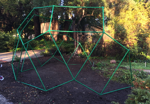
When the drought killed a bush giving us privacy, I decided to replace the bush with a geometrical trellis made of PVC. I thought a zomeball would be a nice shape, and I realized that I could make the connectors easily from PVC elbows. Needless to say, I designed my trellis in vZome, then built a scale model with real Zometool.
It may not be obvious, but all the vertices in this figure are equivalent, discounting omitted edges on the boundary. Each vertex joins two opposing rectangles, a pentagon, and a triangle. This means that a single type of connector can be built, just by joining two right-angle PVC elbows in a very precise way. After that, the design simply calls for two lengths of PVC pipe, related by the golden ratio.
Achieving that precise angle is an easy job for a standard mitre saw, once you know how to set the angles. I used the vZome model below to determine the mitre and bevel angles for my saw. The red square indicates the cut that needs to be made.
The purple rectangles represent the planes of the two right-angle connectors. The rectangle with an adjoining green triangle represents the saw platform. Assume that one leg of the right angle is up against the saw fence. The mitre angle is then represented by the green triangle (and the red strut). It is therefore equal to arctan( 0.618 ) = 31.7 degrees, since the two blue struts are related by the golden ratio. The bevel angle (or rather, its complement) is represented by the orange triangle. Since the orange struts are separated by 72 degrees, the bevel angle is 18 degrees.
Here you see the saw with bevel and mitre angles set. Serendipitously, my mitre saw (like most) comes with a special detent for a mitre angle of 31.6 degrees, for cutting crown moulding... close enough to 31.7 that it does not matter. You can see the marking at the bottom of the photo.
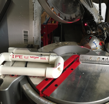
In the picture above, you can see my initial approach for a "jig"... a simple rectangle with four elbows. However, for the opposite mitre angle (which is half of the cuts), the end of the elbow was past the end of the fence, so the jig failed to guarantee the angle. I modified the design as shown below, just by incorporating some straight connectors. I also changed my approach so that all cuts were made with the material to the right of the cut, since my saw's laser delineates that side of the saw cut (the "kerf").
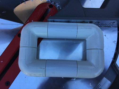
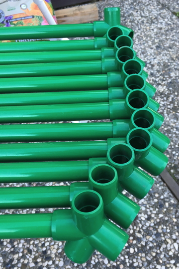
Each rectangular assembly recieves four cuts, two with the mitre angle set to the right, and two with it set to the left. Obviously, you want to make all the right-handed cuts at once, then change the angle for all the left-handed cuts, or vice-versa. To do that, you'll want enough straight connectors (and very short pieces of PVC pipe) so that you can make rectangular jig assemblies for all your elbows at once. Obviously, each jig assembly produces two of the "butterfly" connectors, shown below before cementing.
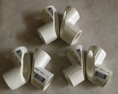
The connectors shown above were from my initial test, and I was cutting too deeply into the elbow, with the result that the "triangle" ends (pointing up, in the photo) cannot support PVC pipe inserted more than 1/4 inch.
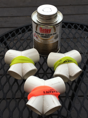
Although clear PVC cement is harder to work with than the usual blue color, it is worth it to avoid the unsightly color on the finished pieces. Stout rubber bands serve well enough as "clamps" while the bond forms. An important trick: have a flat surface at hand so you can get all four ends in the same plane before the bond finishes! Remember that the cement bond forms in about 15 seconds, so be sure to buy and cut extra elbows so you can afford some mistakes.
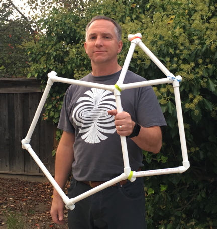
Plan on lots of practice runs and proofs-of-concept. PVC cement is unforgiving, so if you get your angles wrong, or your orientations, or whatever, you'll be sorry. Here I'm proving out my connector angles in a temporary structure, just confirming that I can make pentagons, triangles, and rectangles.
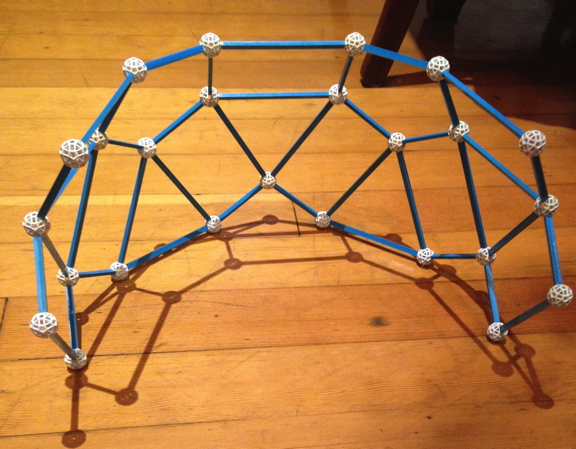
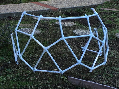
The next step was a scale model, about 2-1/2 feet high. This model allowed me to prove out the entire assembly process, before investing in the more expensive "furniture grade" PVC for the final structure. It was extremely useful to have this model for engineering the build itself, since it is very easy to get the connectors incorrectly oriented, or to build a non-planar rectangle or pentagon. Designing the process was half the fun!
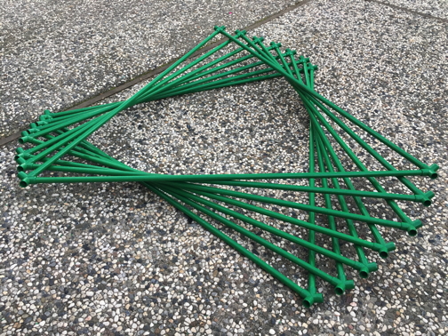
Another part that was fun: cutting PVC pipe! A ratcheting PVC cutter is one of the most satisfying tools I've ever used. Even my 12-year-old daughter enjoyed it, since it made her feel powerful, I assume. No matter how fun it is, though, it was great to have help for all the cuts required.
Having worked out the bugs, it was time to order the final material. There are several suppliers. I was happy with my order from Pipeworks. Furniture-grade PVC only comes in 5-foot lengths, so you have to keep this in mind when designing a structure. I ended up cutting off about 4 inches for my long edges, just to achieve the scale and rigidity I wanted. My trellis uses 1/2-inch internal diameter pipe; it is fairly "spongy" with that size, though, and may eventually sag under the weight of vines.
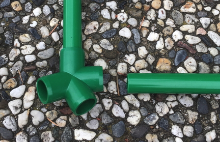
Part of my assembly process design involved uniformly attaching a single connector to each long pipe. The regularity helped me avoid orientation errors.
Avoiding non-planarity is another trick. Since you can't really mess up a triangle, I did these first. Even here, notice that I still had to be careful with connector orientation, though the preceding step minimized the risk. Of course, I did a "dry" practice run first.
For the top edge of my trellis, the adjacent triangles were omitted, so I had to find another trick to help with orientation and "twist". It turns out that a driveway (as an approximate plane) is a pretty good way to make sure that two ends of a rectangle are parallel.
Final assembly of the structure was a two-person job, but was almost error-proof in my design. One non-critical consideration was to minimize the number of ladder moves while doing the cementing on the top edge junctions. (Yes, I'm an efficiency nerd.)
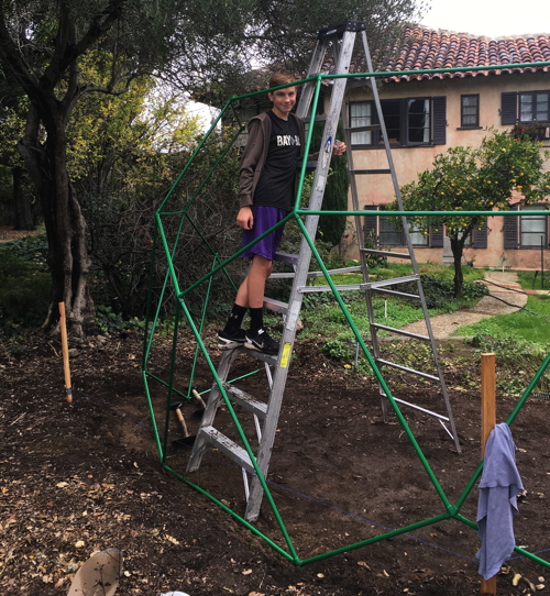
The largest piece of work in the whole project hasn't even been mentioned yet: leveling the ground in preparation. My son was invaluable here, too... turns out that he likes to dig!
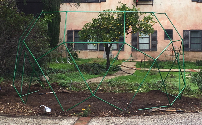
Since I wanted to allow for future expansion (to a dome, perhaps), I left the boundary connectors open. However, not wanting the pipes to fill up with water, etc., I purchased enough end caps to plug all the holes, though without cement.
Now, we have to find the vines we want to grow, and make the structure a bit more pleasing to look at... I suspect the neighbors are not delighted with the giant green sculpture!